
The power supply is very straightforward. The mains enters via a filtered IEC inlet and powers two 30VA toroidal transformers. These connect to the power supply PCB, which generates two separate ±15V supplies for the main analogue PCB and the surround PCB. The +5V logic supply and the +12V relay supply is also generated here, and there is a mains-fail detect circuit which controls the output muting relays.
There is no mains power switch as the unit is intended to be left powered up continuously. While in standby, all circuits remain powered apart from the VFD display. Fortunately, the preamp doesn't consume much power, so it shouldn't adversely affect my electricity bill [while perhaps fair enough in 2002, I definitely wouldn't say that today!].
The analogue supplies are regulated by LM317T/337T ICs. I chose these for their improved regulation and lower noise output compared to 7x15 types, plus, should it become necessary, they provide the option to vary the supply voltages. The 12V +RELAY supply is regulated by an LM2940, which is a low-dropout 12V regulator - meaning that hopefully, a mains dip shouldn't cause the record-out relays to drop out and affect a recording (assuming the rest of the equipment holds up). I felt that it was definitely worth regulating this rail because apart from that reason, it ensures that the relay coils are fed with a clean supply, eliminating the possibility of hum and noise being induced into the audio circuits. Finally, for the logic supply, a standard 7805 is used.
The regulators use the case as a heatsink - they are bolted onto a nicely-machined length of aluminium which is in turn bolted to the bottom panel.
In addition to the basic regulation and mains-failure detection, the PSU PCB serves one final purpose - to separate the serial control connections from the 34-way ribbon cable and pass these through to the control PCB via the black connector on the right.
)
)
Although it would have been possible to derive the logic and relay supplies from the same transformer used for the analogue supplies, it would have resulted in increased dissipation due to the greater voltage drop across the regulators. The VFD takes between 150 and 200mA, which is significant. Also, purists will assume that this will automatically affect the audio signal, and that isn't totally impossible. The main advantage of separate transformers, or separate windings on a single custom-made transformer in the real world, is ground management. The issue of avoiding earth loops and minimising digital breakthrough is complicated to say the least!
Ideally, the analogue and digital grounds should only be connected at one point. The PGA2310 datasheet suggests that this is close to the IC, so this happens on the main analogue PCB. Having the PIC on a separate board helps, and when the PGA2310s aren't being addressed there is no activity on their serial control bus. A common trick to achieve further isolation is to use opto-couplers to electrically isolate the digital and analogue section - I didn't feel that was required here as I couldn't detect or provoke any digital breakthrough on the PGA2310 test PCB.
Power failure detection
The mains-fail detect circuit is based on good old-fashioned transistors. This is because you can predict exactly how they will behave during power-up and power-down, which is not necessarily the case with CMOS or TTL logic! The main function is to control the un-mute relays, as discussed on the control systems page, but there is also an active-low PWR_FAIL output that is passed to the control PCB - this causes a power-fail interrupt in the PIC which writes the current program state to EEPROM during the brief hold-up time before the power supply capacitors discharge.
This gives another option - the PIC could pull down the PWR_FAIL line, which will drop out the un-mute relays, disconnecting the power amps from the outputs and reducing power dissipation slightly. This could be used during Standby, after a routine dump-to-EEPROM has occurred (as obviously the PIC won't be able to respond to the PWR_FAIL signal in this state). This neatly saves tying up another port on the PIC and having to run an extra signal between the PSU and Control PCBs. I never implemented this, but it's something I'd definitely do today, given the price of energy (the 4 muting relays add up to nearly a watt of energy). I'd also shut down the analogue circuitry too. It all adds up...
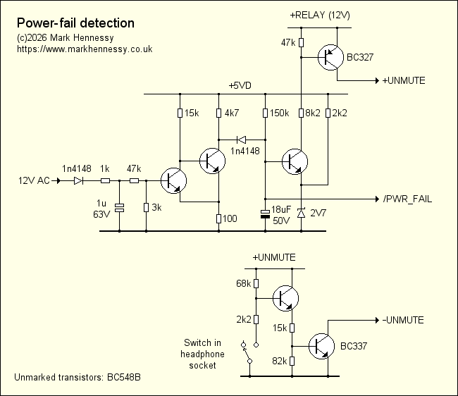
The 12V AC winding is half-wave rectified and a DC potential is established across the 1µ capacitor. This voltage is presented via a potential divider to the 2-transistor Schmitt trigger. The values in the divider are chosen to ensure a power-fail condition is signalled when the mains supply falls to around 200V.
This method of detection is not as fast as circuits that discharge the timing capacitor with every mains cycle, but it works well enough here. In practice, I don't think I've ever noticed a drop-out in normal use.
Incidentally, many years ago I saw someone on a forum question the use of the 2V7 Zener diode. I was surprised that none of the replies gave the correct answer, which is simply to allow the circuit to work!
If the third transistor's emitter was simply grounded, it might never be
able to turn off. That's because the collector of the second transistor
can't quite get to 0V because of the 100Ω resistor that introduces
the necessary hysteresis. But even if it did, the 1n4148 would still
prevent the 3rd transistor from switching off, given that you
need comfortably less than 0.6V at its base. Lifting the emitter of the
3
For completeness, this diagram also shows how the -UNMUTE rail is generated, although these components are located on the main analogue PCB. I could have just used the switch contacts directly, but thought it was worth buffering them, and in this arrangement any problems with the switch contacts will tend to turn on the relays and allow sound through rather than muting. It also saves having to run an extra wire to the headphone PCB to carry the current of the relays - as it is, the return current is very small so it's no problem to allow it to travel along the screen of the 3 core cable joining the PCBs.