Back at the beginning of this project, the analogue stages were probably the least interesting part of the preamp. A simple gain stage following a pot and some relays, something that has been done a million times before... But, adopting a 6-channel input changed all that...
I quickly gave up trying to find a 6 channel motorised pot, but not before considering a number of horrible mechanical contraptions to join 3 stereo pots! On balance, it was probably a good move - my 'market research' suggested that the cheap pots are not worth considering - all the surround receivers that I investigated had terrible tracking at lower volumes. And, even if I'd managed to find a half-decent pot, I still had to introduce offsets for surround level balancing...
Electronic volume control
 Initially I
thought some kind of VCA (variable-gain-amplifier) would be
the way to go. But I was surprised at how few are out there -
and most aren't really suitable for hi-fi.
Initially I
thought some kind of VCA (variable-gain-amplifier) would be
the way to go. But I was surprised at how few are out there -
and most aren't really suitable for hi-fi.
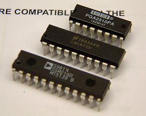
The SSM2160
The most promising VCA IC I found was the SSM2160 from Analog Devices - a serially-controlled 6-channel device, specifically designed for multichannel home-cinema applications. Of course, the serial interface might be a problem for some DIYers. But this is a really good incentive to learn PIC programming, as this opens up access to a whole range of ICs that can't realistically be controlled from CMOS logic!
Internally there are 6 independent VCA sections. The control voltages for each of these are derived from DACs which are addressed via a simple serial interface. Each VCA input is fed from the sum of the master DAC (which is 7-bit, resulting 128 levels of a nominal 1dB step size) and a 5-bit channel offset DAC. This makes programming easy, as all the offset calculations are essentially performed in the analogue domain inside the IC... Nice.
But, the maximum input level for reasonable distortion performance is given by AD as 1.8V RMS, meaning that the signal should be attenuated before being applied to the IC. As a result, more gain would be required on the output amps, compromising the S/N ratio. When you start to think about the potential additional gain that a surround offset adjustment might give, you realise that the gain/headroom management is quite tricky... Also, best-case distortion at 1kHz is 0.01%, which is rather much for a high-quality product.
Digital Potentiometers
After being underwhelmed with the audio performance of the SSM2160, I started researching digital potentiometers. Essentially, they contain a chain of resistors, and a giant analogue multiplexer controlled by internal logic (normally shift registers fed from a simple serial interface) to select the appropriate tap from the resistor chain. Generally, these aren't really intended for audio use as they have linear steps, which means fun and games to approximate a logarithmic taper. However, there are exceptions...
The DS1802
An interesting digital potentiometer is the Dallas DS1802. Control is by 3-wire serial, or by simple up/down pushbuttons. There are 65 positions (including mute) and the step size is 1dB. This isn't really enough range for this application, but this IC might be a good choice if you've managed to find a 6-channel pot, and just need to provide surround-level adjustments.
The audio performance looks good on paper - the THD is around 0.002% at 1KHz, rising to 0.02% at 20KHz. It has zero-level crossing detection to minimise audible switching artefacts. The main issue is that the IC is powered from a single 5V supply, which will result in headroom problems...
The LM1972
The next example I found was the LM1972 from National Semiconductor, a dedicated 2-channel audio attenuator... When Farnell stocked them, they were quite pricey (£6.85+vat for <10), especially as I would have needed 3, but luckily National Semiconductor were happy to send me a couple of samples for evaluation.
These devices work well, being easy to drive serially. They have a 78dB attenuation range which is in 0.5dB steps down to -47.5dB (below that the steps are 1dB). Sending them a value larger than '78dB' results in a Mute condition. The output must be fed into a very high impedance to avoid loading the resistors and affecting attenuation accuracy. This means a FET-input op-amp buffer, which resulted in another bout of research to find an alternative to the NE5532, arriving at the OPA2134 (despite some minor reservations voiced on the Self Site).
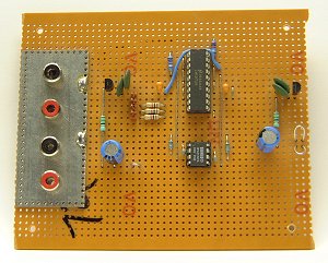 The audio specs
looked promising, so the next step was to build up a test-board
and interface it to the PIC board. Once correctly working it was
wired into the tape-loop of the hifi to test - I had a few
worries to eliminate, and this seemed like the easiest way...
The audio specs
looked promising, so the next step was to build up a test-board
and interface it to the PIC board. Once correctly working it was
wired into the tape-loop of the hifi to test - I had a few
worries to eliminate, and this seemed like the easiest way...
For example, was 78dB enough range? The answer was "probably"... It is very quiet around here at night, and it's surprising how loud -78dB could be. I decided that I'd add a -20dB function (a simple attenuator switched by a relay) to give some extra control.
Another problem occurs when you introduce offsets for the surround channels - suppose you wind the centre channel up to +10dB, and turn the rear levels to -10dB. This means that when the master volume is above -10, the centre channel will have hit an end-top and will be unable to increase. The same happens at the bottom end, with the loss of the rear channels during a late night (quiet) film! My initial plan was to have a set of LEDs in the display window that light up to show the operating channels (like the Tag McLaren AVR-32) - then if any channel does hit an end-stop, the LED could change colour to warn of this...
One final problem with this IC was digital breakthrough. Having studied the datasheet and following all the precautions to avoid pops and bangs at level changes, I was disappointed to hear low-level clicking noises as the volume was changed. Examining the waveform on the scope revealed that the digital control signals were finding their way onto the analogue outputs. Since this, I've been working on the assumption that this is a problem with my Veroboard test board (despite taking what precautions I could with the layout), and that a proper PCB with more careful layout will suffer less from this problem...
The CS3310
Despite more-or-less settling on the LM1972, I discovered that a popular choice is the CS3310 from Crystal Semiconductors. This is a nice IC and is used in some expensive kit from Tag McLaren and others. It has a total control range of 127dB, with a 0.5dB step size over the entire scale. To achieve this massive range, two separate resistor ladders are employed - first an attenuator is on the input in similar form to the LM1972 to provide 0 to -95.5dB of attenuation. Secondly an internal bipolar op-amp, configured in non-inverting mode, provides 0 to +31.5dB of gain. All of this is transparent to the system controller - you tell it what value of gain you want (where 1 is -95.5dB and 255 is +31.5dB) and internal logic will programme up the two controls as required. Obviously, the op-amp works in unity-gain mode when possible to minimise noise...
The LM1972 data sheet warns that popping noises might be audible when changing gain settings under certain conditions. To avoid this problem in the CS3310, it includes zero-crossing detection. Also, it includes a mute function that is invoked by sending zero to the device serially or driving a pin low. There is an internal DC offset calibration+elimination cycle that is explained by the datasheet.
Another really nice function is the pin-out. Really! The analogue and digital pins are on opposite sides of the chip meaning you can have the device straddling the two ground planes, making PCB layout much easier. This matters when you have to design them!
The only immediate problem with the device is the low supply voltage - ±5V. As with all devices considered so far, careful gain/headroom management is required...
The PGA2310
Just as I was wondering who might be able to sell me the CS3310, Texas/Burr-Brown released the PGA2310. This brand-new IC is pin and software compatible to the CS3310 and is pretty-much identical apart from being able to run from ±15V analogue power supplies. According to the data sheets, a number of the key parameters seem improved as well. Not only was this IC perfect (on paper, at least), but Texas have an excellent samples policy. Three were UPS'd to me within a day or two of making the request!
The advantages of this IC over the LM1972 are clear. I can provide the surround-level adjustments without hitting endstops. An 'input-trim' function can be added to equalise the different levels from my sources (a common function these days). In addition, the master volume control can have a bit more range.
Just one question-mark: the PGA2310 is so new that I'm worried about the possibility of future problems. The CS3310 seems to be a well-established IC that is used by plenty of people in expensive, well-reviewed equipment. The PGA2310 might have disadvantages compared to the CS3310 that aren't apparent from reading the data sheets. It might also be discontinued if hi-fi manufacturers understandably decided to stick with their implementations of the CS3310. Internet research finds nothing but praise for the the CS3310, and very little about the PGA2310...
So, the conclusion is that I should attempt to cover myself in the event of these potential problems. In practice, this is simple - the only real difference is the analogue supply voltages, so if I incorporate local regulation for the volume control stage (which would be a good "Marketing" ploy in the real world ;-), it would be a simple matter to change the supplies from ±15V to ±5V
Update - 29/4/2002: I've decided to stop worrying about this now. It appears that the PGA2310 has been adopted by some manufacturers, so it will hopefully remain in production. And anyway, I have enough to complete the project.
PGA2310 Testing
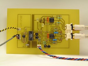 After the digital
breakthrough problems of the LM1972 Veroboard test, I decided
to play safe and have a test board etched. This might seem a bit
much, but I wanted to give the PGA2310 every chance to work
well... Initial results are encouraging.
After the digital
breakthrough problems of the LM1972 Veroboard test, I decided
to play safe and have a test board etched. This might seem a bit
much, but I wanted to give the PGA2310 every chance to work
well... Initial results are encouraging.
As you can see, there is quite a lot on this board compared to the LM1972 circuit - perhaps surprisingly, the internal op-amp doesn't really help to reduce the component-count. The reason is buried in the data sheet:
It is important to drive the PGA2310 with a low source impedance. If a source impedance of greater than 600Ω is used, the distortion performance of the PGA2310 will begin to degrade.
Ok, so the input needs to be buffered first. Well, this isn't a big deal as I was already planning to provide a buffered listen-source output. This actually came about when I decided to include an option to feed a L+R mix to the LFE channel - the summing amplifier would have a low input impedance to minimise thermal noise so it would need to be fed from buffers. All I needed to do was ensure the buffer was of good quality, and feed the PGA2310 from it rather than directly from the output of the relays...
As the PGA2310 has an internal op-amp, surely I don't need another op-amp after it? Well, maybe not. But, while the internal op-amp is advertised as being happy to drive 600Ω loads, the THD performance naturally degrades slightly. The NE5532 is excellent in this respect, as shown by Self. If this was an integrated amplifier, containing a power amplifier of known characteristics, we probably could omit the the buffer. But this needs to work in the real world, and there's a slight risk of me building a set of power amplifiers at some point in the distant future. If I do, they will almost certainly have a low input impedance (read Self's Audio Power Design Handbook for the reason!).
Another consideration is a matter of future maintenance. Any IC that is directly connected to the outside world is automatically at risk from all manner of assault. Hence, it should be (a) socketed, and (b) easy and cheap to replace!
Finally, consider the matter of obsolescence discussed above. Should I need to replace the PGA2310 with a CS3310 at some point in the future, remember that it has less headroom. So the option to provide a 6dB boost in the output buffer might be useful.
Here's the schematic of the test PCB, minus the supply rails and digital connections for clarity. Click to enlarge...
)
Gain/Headroom and Bandwidth Management
A deceptively complicated subject. First, consider bandwidth. Obviously the preamp will need to have a flat frequency response to beyond the accepted limits of hearing which obviously comes by default with modern devices and techniques. Indeed, these days, instead of striving for a flat and extended frequency response, you have to positively control of the response at the frequency extremes to avoid problems with DC or ultrasonic noise. As a famous audio designer once said, the wider you open the window, the more dirt flies in!
The average CD player (or any digital source) will generate considerable amounts of ultrasonic noise. Even an FM tuner or phono pickup is a possible conduit... In these days of cell-phones, "Wi-Fi" and Bluetooth, you cannot ignore the issue. The priority is to stop the noise getting to the first op-amp, where it will be handled in a very non-linear fashion. Or, to put that another way, demodulated.
The input ultrasonic filter should be high enough in frequency to not overlap with the subsequent bandwidth limiting to keep the system bode plot 'simple'. So why can't the system -3dB cut-off frequency be set by the input ultrasonic filter? Quite simply, as you don't know the source impedance, you can't accurately specify the frequency. With the component values shown above, here's how the -3dB point varies with source impedance:
| Zsource | HF -3dB point |
|---|---|
| 0Ω | 377KHz |
| 100Ω | 360KHz |
| 600Ω | 293KHz |
| 1K | 256KHz |
| 10K | 75KHz |
This might not be a problem for some applications, but the perfectionist in me prefers a nice, well-defined bandwidth. So this is set later - after the PGA2310. In theory it could be done before the PGA2310, but remember that it has to be fed from a source impedance of <600Ω, so at frequencies above the passband, the op-amp would see a low-impedance load - not a big problem, but not ideal...
LF is subject to similar problems. There are several points in the system that require DC isolation, but it is especially important that the subsonic filters are well away from the required -3dB point because modern audio and movie soundtracks contain lots of very low bass output, and the affect of several cascaded 10Hz filters will cause significant drops higher up, say at 30Hz.
Unlike the input ultrasonic filter, using the input DC blocking capacitor to set the system response is feasible. Here's the calculated -3dB cutoffs versus Zsource with the component values shown:
| Zsource | LF -3dB point |
|---|---|
| 0Ω | 1.9Hz |
| 100Ω | 1.9Hz |
| 600Ω | 1.88Hz |
| 1K | 1.87Hz |
| 10K | 1.7Hz |
On the test board, the -3dB point is set to 5Hz after the PGA2310 - this ensures that there isn't a rise in distortion at L.F. - but as the DC offset at the output of the PGA2310 is very low (<3mV), even at high gain settings, I can probably DC-couple the output straight into the output buffer, which will have a capacitor-coupled output in the final product.
Gain and headroom are also important system parameters to get right. Obviously, you need to avoid unnecessary attenuation followed by amplification, as that will reduce the system signal to noise ratio. When using conventional potentiometers and op-amps, there is rarely any excuse for this fundamental error. However, the picture is complicated when using solid-state control as the ICs have rigid headroom limits.
Consider the CS3310, which has a maximum input and output voltage of 3.75V peak, or 2.65V RMS. Over the years, the output level of CD players has crept up in an attempt to give a subjective advantage over players that stick the nominal 2V RMS output - I certainly wouldn't be all that surprised to find a CD player that has an output of 2.6V RMS. Personally, with this IC, I'd want to add 6 or 9dBs of gain in to the output buffer to improve the output headroom of the system, and attenuate the input by a similar degree. Of course, there will be a noise penalty with this...
Obviously, the PG2310 doesn't have this voltage limit, and is able to offer 9.5V RMS from ±15V supplies. This means essentially unity-gain input and output buffers can be used. Note also that similar games would have been required with the LM1972 if I'd employed that...
DC issues
Upon completing the test board and ensuring it worked, the first thing I noticed was clicks and pops heard through the speakers while making volume adjustments. This was disappointing as the IC is meant to have zero-crossing detection to prevent such problems. Interestingly, these noises were much worse when the IC had gain rather than attenuation. So presumably, the zero-crossing detection wasn't working; to test this theory, I applied a low-level sinewave of around 30Hz (turning the bass to minimum on the workshop hi-fi) and found the effect was much better. Next I put a DC-coupled 'scope across the output of the input buffer, and varied the level of the input signal, clearly demonstrating that when the sinewave was large enough to cross zero, the clicks and pops went away. There was some -20mV of DC offset from the input buffer, caused by the input bias currents of the NE5532, and this was enough to cause these probles.
At this point I began to wonder if I would have to include AC coupling between the input buffer and the PGA2310. This is obviously undesirable - the capacitor would have to be a large electrolytic to avoid the rising LF THD described above...
The final answer was simple - use an OPA2134 for the input buffer. The FET-input stage results in less than a millivolt of offset, and the behaviour is much improved. As I mentioned earlier, Doug Self found some issues with this IC, but to be honest I think I can compromise here. Obviously, there are plenty of horrendously expensive ICs that might be better, so that's a subject for future research...
The output NE5532 causes a similar DC offset on the output. However, this isn't a problem if the output is AC-coupled (using a large electrolytic bypassed by a non-electrolytic). That said, if I decide to use the input capacitor to define the system LF -3dB point, I can DC-couple the PGA2310 to the output buffer and this will reduce the offset, so there is a chance of omitting the output capacitors...
Muting
The two resistors on the output network might look a bit odd, but that's because of my cunning 'soft-mute' system which will be included on the final PCB... This is for power-up/down (and headphone listening) conditions, as the mute capability of the PGA2310 is good enough for normal operation, helping to reduce mechanical relay noise, and simplifying the muting logic. If I'd stuck with the LM1972, I would have had to mute the surround channels with relays when another input was selected as the software mute wasn't completely silent.
Some muting systems simply short the output to ground (a) - that results in a possible DC 'thumb' from the speakers, and unnecessary dissipation in the buffer amp if it has a decently low output impedance. Other systems allow the output to float - bad idea for obvious reasons. There are many variations, the most common of which short the output to ground while disconnecting the output buffer (b). This is used in the Self Precision Preamp '96. While it's better for the op-amp, the power amp is presented with a brief open-circuit during switching, and there's the potential for rather loud noises when (not if!) the relay contacts get 'dirty' with age.
My small variation on the scheme (c) presents the same impedance in either mute or umute, which might be important with DC-coupled power amps. These are a bad idea IMO, but they exist. The inclusion of the 820Ω resistor deals with the in-between state during switching (or a dirty contact). The network becomes a -5dB attenuator (ignoring power-amp impedance) with a 500Ω output impedance. This is still a jump, but obviously better than infinity that the normal scheme provides, and will alert me to dirty relay contacts in a much more polite fashion than (b). (I'm speaking from experience!)
Finally, the preceding DC-blocking capacitors can charge quickly via the 820Ω resistor - with the large values envisaged, this is a worthwhile advantage. The only penalty is 0.8dB of headroom due to the attenuator formed by the resistances. Also, the 1K1 resistor 'robs' the buffer of a small amount of drive capability, but if that's an issue in practice then different values can be chosen. I just liked them because they form exactly 100Ω (Incidentally, 56Ω and 470Ω are very close to 50Ω, but that's a bit low for an unbuffered NE5532)
Misc Details
There is a small loss in the input filtering, and this is accurately compensated by the gain in the first op-amp. This is perfectionism striking again, as I wanted the buffered listen-out to be the same level as the input! When I build the surround module, I suspect I'll not bother, and make up the 0.39dB in the output buffer. Currently the output buffer is unity-gain, but that will change as it has more headroom than the PGA2310 - especially as 1.45dB is lost in the -3dB setting network shown...