
The preamp control system is based on a PIC16F877 which controls relays and the volume control ICs via simple serial interfaces. These interfaces are only active when processing commands, resulting in minimal impact to the audio signal. In addition, the output muting relays are controlled by a power-fail circuit that is independent of the firmware running in the PIC.
Display
I thought about the choice of display for a long time... as mentioned before, I had some difficulty finding a suitable LCD display that could be clearly read from across the room without looking too horrible close-up. Part of the problem was caused by sitting at an angle to the hi-fi, causing a loss of contrast.
Also, market research suggested that LCDs are a bit 'lo-end', as very few quality products use them. So, despite the cost, I decided to buy a vacuum fluorescent display module. It's an excellent device, being compatible with the industry-standard LCD interface, making it a drop-in replacement. It incorporates an onboard DC-DC converter, so it only requires a single +5V supply. There's no need to provide a contrast adjustment, and the display brightness is controlled by software, all of which simplifies the control hardware...

This is the 16 by 2 display that I bought initially, but I decided to use a 20 by 2 unit in the final project.
Another advantage of these displays is the huge range of display colours as there is a reasonable spread of energy across the visible spectrum. Filters let you change the default blue-green to almost any colour you like. Here are some of the better choices:


Graphic VFD Module
Just as soon as I finished the preamp (autumn 2002), Noritake-Itron brought out a new range of graphic VFD modules that were uncharacteristically affordable. Typical! However, I quickly noticed that the GU140X16-7002 had very similar physical dimensions to the 20-by-2 text display that I was already using. Now very interested, I saw that the interface of the unit was a relatively straightforward 8-bit affair, and as I had some spare ports on the PIC, I guessed that with some simple mods to my control PCB I could somehow incorporate the new module.
Then I noticed that Farnell had just started stocking some of these new displays, but their GU140X16 had a -7806 suffix instead of -7002, which apparently signified an LCD-compatible design (just like my existing text only display). Ok, it wasn't quite as powerful as the -7002 (fewer fonts and graphics commands), but it would drop straight into my preamp with no modifications at all...

This picture shows the GU140X16G-7806 next to the CU20025ECPB-U1J
text-only module. As it turned out, the physical dimensions are completely
identical - even the 14-way ribbon cable connection is in the same place!
Thank you, Noritake-Itron! And the price? Including VAT, £40.
Virtually the same as the text-only unit. The Farnell part number is
412-8795 121-6682 (£38.99+VAT - checked autumn 2009).
Though they don't appear to be widely available today (August 2026) - they
are shown on the Noritake Itron website, so there is hope if you really
wanted one. But today, TFT and OLED displays have largely taken over.
Check out the User-Interface page for some screen-shots.
PIC Upgrade
Another key stage in the development was to find a larger PIC. It wasn't long before the 16F84's 1K program memory and limited IO became a problem, so I made the brave step of buying a 16F877. This really is the Rolls Royce of midrange PICs, and is very affordable (£5.65+VAT from Farnell - 976-1349). As well as a massive(!) 8K program memory, there is much more RAM and EEPROM available, and many more peripherals, including an 8-channel ADC
This device is serially programmable in the same way as a 16F84 - for development purposes I made an adapter cable that plugs into the 18-pin socket on the PIC programmer and a header on the test board. There was a bit of a learning-curve, mainly because many of the new peripherals are enabled by default and if you want to use the IO ports as standard ports, you have to explicitly set them up at the start of your programme. Then you have to learn all about memory management and PCLATH, etc, etc. All the information you need is in the excellent data sheet, but at 215 pages it's hard work! You definitely need a paper copy, so you'd better buy a ream of paper if you can't persuade Microchip to send you a hard copy...
The device led to an instant simplification of the hardware compared to my prototype 16F84 circuit, and an expansion of the user interface...
;)
)
The prototype mounted onto some timber offcuts...
)
The 16F877 has reduced the component count somewhat!
)
A touch of luxury - the £30 rotary encoder (see below).
Circuit details
Referring to the complete schematic, you can see that the control circuit is very straightforward. Note that there are only 12 connections between it and the rest of the preamp - this is the big advantage of serial control. If I'd located the source-select relay drivers on the control board then the numbers of connections would have doubled.
)
The PIC runs at 4MHz and requires no external reset circuitry.
)
Top view of the control PCB. At this point I was awaiting delivery of an 18 pin socket for the Darlington driver IC. It took a seriously long time to design this layout, but I ended up with surprisingly few links given the complexity.
)
This bottom view shows the intricate layout plus a couple of SMT devices. As the PCBs were hand-etched, I didn't want to go much tighter with the design rules.
Local switches
Rather than separate or multiplexed IO lines, I decided to use the ADC on the PIC. This means that each switch presents a different voltage to the ADC, and software decides which switch was pressed and determines if the switch is pressed, held or released. This port is measured every 30mS, and a valid keypress is determined from 3 of these samples. The routines to do this caused much headscratching, but I'm pleased with (or proud of, even!) the final result. Sony for one use a similar scheme in some of their products, so it's nothing new, but it's an excellent way of simplifying hardware, and also a good learning experience...
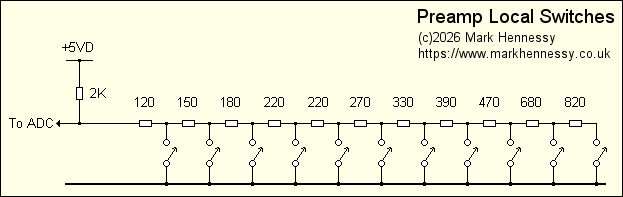
The resistor values chosen result in a voltage that differs by 0.3V as each switch along the chain is pressed. The resistor values to do this turned out to be nice, round E12 preferred values, which was pleasantly surprising. As current consumption isn't an issue, I decided on relatively low values for good noise-immunity. If this was a battery powered instrument, I'd consider using values from the next decade.
I've provided a test point on the PCB for the input to the ADC - this might prove useful for faultfinding in the future... As you can see from the overall diagram, the resistor chain is continued between the two front panel PCBs and this involves several connectors which might become unreliable with age...
Each switch has an integral LED, apart from Store which uses an external LED to light the button. The Standby, Mute, View and Store LEDs are connected directly to ports on the PIC while the LEDs in the input switches are driven by a shift register which is surface-mounted on the switch PCB and daisy-chained from the UDN5821 relay drivers. Apart from saving interconnections between PCBs, this has the advantage of being able to display completely different states compared to the input select relays. This brings two distinct benefits:
- The relay drivers can have arbitrary output assignments. This means that the pinout of the relay drivers can be chosen in a manner that is most convenient for PCB layout; a look-up table in the firmware translates a source number to a physical pin on the ICs. This of course also applies to the LEDs in the input select buttons.
- The enabling of a "Listen-Source" option to the Record-Out menu. With this selected, the Minidisc and Tape buttons become tape-monitor switches.
This second point worked out rather neatly - when enabled, the record-out relays follow the listen relays unless you want to listen to a tape-loop - thus providing genuine tape-monitoring. Another minor feature that I'm considering adding to the software is to use the source LEDs to echo the Record-Out selection when you are in that menu mode. As well as making things seem slightly clearer, the input select buttons could be used to change the Record-Out selection (this would be in addition to turning the rotary encoder)...

The left-switches PCB: Standby and input source switches and the IR receiver...

Surface-mounted shift-register and tantalum decoupling capacitors...

The right-switches PCB: Mute, View and Store switches - the PCB layout provides the option to fit a different Store switch if required.

The Store LED bodged on the back of the PCB - should have used a surface-mount device!
Volume control
The volume control is a rotary encoder. I'd experimented fairly
successfully with the cheap contacting versions, but on rescuing an
expensive optical unit from the skip at work, I was immediately won over
by the superior mechanical feel of the device (the Clarostat
120EN-128-CBL). Given that it is the most frequently used control, I felt
it was worth the expense. Unfortunately, the rescued device only worked
for a few minutes at a time, and my repair attempt just resulted in more
damage... Farnell sell them (part number 328-2338 114-4747) for
£30+VAT £41.04+VAT - hopefully today cheaper
alternatives might be available...
The optical unit has a high resolution of 128 cycles per revolution, which is quite good fun for volume adjustment, but useless for driving the menus. I've implemented software-controlled tracking speed, so the resolution is reduced to around 20 cycles per revolution when in a menu mode. The resolution in normal (volume) mode might be a user-option eventually...
The device uses the RB4 port change interrupt, and has protection resistors to prevent damage when the circuit is first powered up (in case the PIC tries to assert a state before the software has configured the two IO lines to be inputs)
Update - another encoder failure!
Given that the encoder I rescued had failed, perhaps I should have been cautious about buying the same model, but random failures happen so I gave it the benefit of the doubt. But after some 10 years, my encoder also failed, in exactly the same way. So time to find an alternative.
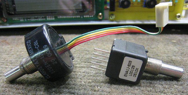
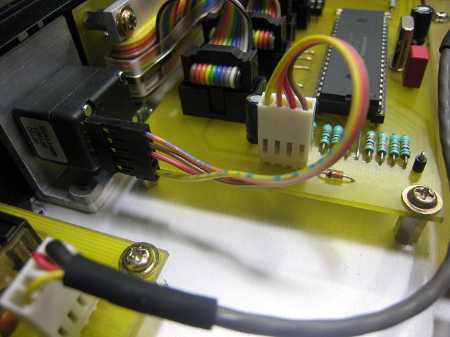
I settled on the Bourns ENA1J-B28-L00128L, which is very similar to the Clarostat electrically, but is physically smaller. The bushing and shaft are the same, so it was a simple swap. This unit has pins rather than a ribbon cable. Rather than solder to it, I made up a simple adaptor cable.
Remote control
The hardware for this is nice and simple - an integrated receiver/preamp produces nice TTL-compatible pulses which are fed into RB0. The firmware uses the RB0 interrupt to decode the Philips RC5 commands. The preamp is mounted on the left-switches PCB and is decoupled by a surface-mount tantalum capacitor. These integrated IR receivers are fairly ubiquitous; for example, see Farnell 414-2822, which costs £1.97+VAT at the time of writing.
Muting
Something that is worth paying close attention to, especially as there will be several power amplifiers connected directly to the unit. The possibility of damaging these, your speakers, or indeed your hearing must not be overlooked!
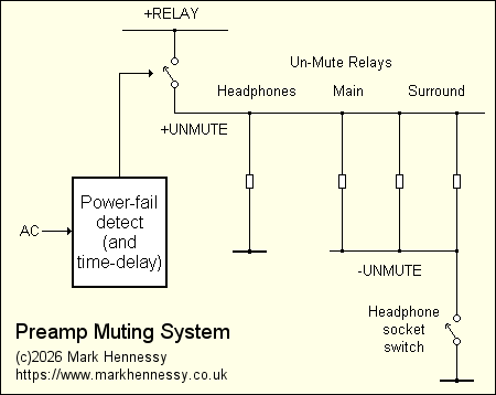
There are muting relays on all power amp outputs and the headphone output. These are controlled by two distinct circuits - the first is the power-fail detect circuit on the power supply PCB which generates +UNMUTE. This supply is removed as soon as the mains voltage falls below 200V. There is a time-delay before this rail is established, giving the PIC time to reset and address the PGA2310s correctly before the audio outputs are enabled.
The second circuit is controlled by a switch in the headphone socket, and generates the -UNMUTE rail. It's not really a supply rail in the conventional sense as the output of this circuit is an open-collector, but it seems logical to regard it this way. This is connected to all output relays apart from the headphone output (for obvious reasons!).
The circuitry doing the bulk of this is located on the power supply PCB, along with a small section on the main analogue PCB, so it is detailed on the power supply page.
12V Triggers
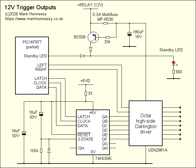
Based around an octal high-side Darlington driver, there are 8 12V trigger outputs available on a rear-mounted 9-way female D-type. While these would normally drive opto-isolated inputs, they are capable of driving moderate loads such as relay coils directly if required.
Two outputs are controlled by spare buttons on the remote control - these are ports on the PIC connected directly to the Darlington driver, but it would have only slightly complicated the code to have just put them on the shift register along with the others, and that's what I'd do today. I planned to interface these to my tuner to provide "Preset Up" and "Preset Down" functions - I did modify my Technics tuner with a 3.5mm socket on the rear and a couple of opto-isolators connected to the switch matrix. The remaining 6 are fed from a shift-register. Three of these are intended to control power amplifiers (main, surround and LFE) and the remaining 3 are set on a per-input basis, controllable by the user.
The Darlington driver is protected by a self-resetting semiconductor "polyfuse" - when in the tripped state a transistor lights the Standby LED at a much greater brightness than normal.
Source code
Many people have emailed to request the source code. However, the source code is not available. Partly because it is far from finished, but mostly because every section of code is original and entirely my own work.
In the future, bits of the code will appear as articles in the PIC section of this site; things like time delays, LCD stuff (writing words, scrolling text, defining UDCs, making bargraphs, etc), serial control of shift registers, remote control decoding... But that will take a long time.
Control Conclusion
After much thought and experimentation, the control hardware turned out to be rather simple. This is thanks to using a PIC with enough ports (meaning the complex multiplexing seen in the 16F84 version was no longer required), and using serial control of most of the preamp. Also, using the ADC for the local switches makes things easier.
On the other hand, simplifying the hardware makes the software more complicated! But, this is normal practice for commercial products - you only have to write the software once, whereas you might have to build the hardware millions of times!
As this is my first 'real' product to use software to this extent, it has been an interesting experience. At the moment the software is basically functional and reliable, but there are one or two functions that I have yet to finish. Also, I keep thinking up new things to add! The bottom line is that this project will remain much more fluid than previous projects, as it will be so easy to add new features and functionality. For comparison, to add a single extra function to my NICAM tuner the control board would probably require a major rebuild!